Thursday, 28 May 2026

Failed Update from Ubuntu 24.04 LTS to 26.04 LTS on Lenovo Thinkpad E16

 I have a Lenovo Thinkpad E16 which came with Ubuntu 22.04 pre-installed, along with a 22.04 recovery partition.

A couple of years ago it updated to 24.04 LTS without any trouble (it must have, because I don't remember doing the upgrade...).

Yesterday I upgraded to 26.04 LTS - the upgrade appeared to run ok (no major errors reported), but it completely failed to boot.

I am out of my depth with regard to modern boot systems with EFI, secureboot etc, so with a lot of help from Google Gemini, I got as far as the following diagnosis....before finally giving up and doing a clean install of 26.04 LTS, which worked fine....

Note to self - don't bother with upgrades, carry on with my previous policy of doing a clean install instead!


Technical Bug Report Summary: ThinkPad E16 Boot Failure and Partition Illegibility Following Ubuntu 24.04 to 26.04 Upgrade
Hardware Environment
  • Device: Lenovo ThinkPad E16
  • Storage: 1 TB NVMe SSD (/dev/nvme0n1)
  • Initial Setup: Factory OEM pre-installed Ubuntu 22.04 LTS, upgraded to 24.04 LTS, followed by an upgrade attempt to the 26.04 LTS cycle.
  • Disk Layout: Partition 1 (p1) as VFAT EFI, Partition 2 (p2) as the OEM Ubuntu 22.04 Recovery system, and Partition 3 (p3) as the main Ubuntu root (/) filesystem.

1. Primary Symptoms Observed
Following the 24.04 to 26.04 upgrade process, the host system became permanently unbootable.
  • GRUB Panic: The bootloader consistently threw an immediate initramfs not found error.
  • GRUB CLI Crash: Attempting to manually execute kernel boot parameters from the GRUB prompt (grub>) resulted in an immediate heap corruption crash: alloc magic is broken at 0x52864020: 0, or halted with error: cannot load image.
  • Firmware Safety Rejection: Attempting to force-boot via the physical device identifier in the Lenovo F12 BIOS menu triggered a hard stop firmware failure: failed to boot both main and fallback entries.

2. Diagnosis via Ubuntu 26.04 Live USB
Booting into an official Ubuntu 26.04 Live USB environment was used as the first primary recovery step, resulting in the following state:
  • Chroot Attempt (Partial Success): The system root (p3) and EFI (p1) were mounted under /mnt. Virtual file systems (/dev, /proc, /sys, /run) were bound.
  • GRUB Reinstallation: Inside the chroot sandbox, grub-install and update-grub completed successfully with zero errors. The kernel and initrd files were verified to physically exist on disk with valid file sizes.
  • The Block Disconnect: Despite successful file writes inside the chroot, the resulting binaries could not be read at actual boot. Testing the configurations via grub-emu inside the Live environment consistently triggered graphical freeze dialogues and returned error: no such device <uuid>, proving that the bootloader parsing logic was entirely breaking when mapping the underlying block device hardware.
  • GParted Warning: GParted explicitly flagged partitions p1 and p2 with a warning stating it was “unable to read the contents of this file system.”

3. Diagnosis via Ubuntu 22.04 OEM Recovery System
Switching to the local, on-disk Ubuntu 22.04 OEM recovery partition terminal provided the definitive diagnostic clue:
  • Complete Metadata Invisibility (blkid failure): While tools like parted and file -s could see /dev/nvme0n1p3 as a raw ext4 volume block, running blkid completely failed to register a UUID or file format signature for the partition.
  • NVRAM Purge (No Effect): Utilizing efibootmgr to successfully delete old cached boot records, remounting efivarfs, and cleanly rewriting a brand-new boot path to shimx64.efi failed to resolve the issue.
  • Lenovo Firmware Cleared (No Effect): Toggling Secure Boot off, clearing all cryptographic Secure Boot Keys in the BIOS, restoring default platform factory keys, and performing a physical Embedded Controller (EC) hardware pinhole reset failed to get the firmware to recognize the partition state.

4. Technical Root Cause Assessment
The upgrade mechanism aggressively applied advanced modern ext4 filesystem features (specifically metadata_csum_seed and orphan_file via updated e2fsprogs parameters) to the main system partition (p3).
  • The Regression: These newly activated features broke backward compatibility with the boot infrastructure.
  • The Result: Because the partition metadata layout changed, the GRUB bootloader encountered unparseable header structures at boot time, throwing memory pointer pokes (alloc magic is broken). Furthermore, it introduced a severe tool pipeline regression where the partition identification layer (blkid) on the older recovery kernel could no longer map or resolve the partition's UUID, rendering standard chroot automated recovery loops fundamentally unviable.

Wednesday, 6 May 2026

GUI Access to Remote Server using VNC

 To view a graphical desktop on a remote server (rather than just having command line access), I do the following.....

Install tightvncserver

apt install tightvncserver

Set Password

run 'vncserver', and enter a password when prompted.

Then shutdown the server with vncserver -kill :1

Set up user desktop

Create /home/graham/.vnc/xstartup which contains:
#!/bin/bash
unset SESSION_MANAGER
unset DBUS_SESSION_BUS_ADDRESS

# Ensure a clean environment for XFCE
export XDG_CURRENT_DESKTOP="XFCE"
export XDG_MENU_PREFIX="xfce-"

# Add this to prevent X from trying to use hardware acceleration
export LIBGL_ALWAYS_SOFTWARE=1

# Start the environment
[ -x /etc/vnc/xstartup ] && exec /etc/vnc/xstartup
[ -r $HOME/.Xresources ] && xrdb $HOME/.Xresources

autocutsel -fork
exec dbus-launch --exit-with-session startxfce4


Start vncserver on boot using a system service

Create /etc/systemd/system/vncserver@.service

[Unit]
Description=Start TightVNC Server at Startup
After=syslog.target network.target
[Service]
Type=forking
User=graham
Group=users
WorkingDirectory=/home/graham
PIDFile=/home/graham/.vnc/%H:%i.pid
ExecStartPre=-/usr/bin/vncserver -kill :%i > /dev/null 2>&1
ExecStart=/usr/bin/vncserver -depth 24 -geometry 1280x800 -localhost -extension GLX :%i
ExecStop=/usr/bin/vncserver -kill :%i
[Install]
WantedBy=multi-user.target

The -extension GLX is important because this suddenly stopped working on Ubuntu 24.04 - it seemed that probing the nvidia hardware was causing security issues which crashed the vnc server.


Set it going with:

systemctl daemon-reload
systemctl enable vncserver@1.service
systemctl restart vncserver@1.service


Set up Client Machine

On the machine you want to use as the client, add a small function to ~/.bashrc:
function start_vnc_tunnel() {
    SSH_USER="$1"
    SERVER_IP="$2"
    LOCAL_PORT="5901"

    echo "Starting SSH tunnel to $SERVER_IP..."
    ssh -L "$LOCAL_PORT":localhost:"$LOCAL_PORT" -N "$SSH_USER"@"$SERVER_IP" &
    SSH_PID=$!
    
    # Give the tunnel a moment to establish
    sleep 2 

    echo "Attempting to connect VNC viewer to localhost:$LOCAL_PORT..."
    # The script now waits here for the vncviewer to close
    vncviewer localhost:"$LOCAL_PORT"

    echo "VNC viewer closed. Killing tunnel (PID: $SSH_PID)."
    kill "$SSH_PID"
    exit 0
}

Then add aliases to use it to access the machines you are interested in such as:

alias oracvnc='start_vnc_tunnel graham orac.local'


Wednesday, 11 September 2024

Re-claiming disk space from mysql database

 Just deleting rows from a mysql database does not tend to release disk space.


This method is drastic, but will get the disk space back:


  1. Extract any data you want to keep from the database (we are about to delete all the records)
  2. select max(id) from <table name>;
  3. truncate <table name>;
  4. alter table <table name> auto_increment=<starting id>;
this leaves you an empty database but the ids generated for new rows will be unique from the ones in the original database rows.

Tuesday, 27 August 2024

VPN for Remote Monitoring

We have just bought ourselves a static caravan and sited it about one hour drive from home - so it is close enough to go there if something needs doing, but not so close that we would call around every couple of days to check on it.

So I wanted a technological solution to allow me to monitor how it is, and in the winter tell it to put the heating on when we set off to go to it, so it is nice and warm when we get there.

The approach I have taken is:

  • Do not rely on the caravan park's internet access, as this is reported to be quite unreliable
    • I am using an old mobile phone with a Lebara sim (£5 per month for 5GB data).  
    • It runs as a mobile hotspot so that several devices can connect to it if necessary - I had to go into the android advanced settings for the hotspot to prevent it switching off after a short time with no devices connected (otherwise an electrical supply interruption can result in us losing communications, even when supplies are restored).
    • This works very well - we have good wifi reception from the phone, even with it in the cupboard at the back of the caravan.
  • Use a low power computer running Home Assistant to do monitoring and control.
    • I had a Raspberry Pi Model 3B available so am using that - it draws about 2W during normal operation.  It has the following main hardware and software components.:
    • Sonoff Zigbee USB dongle (so I can use low cost battery powered zigbee devices)
    • Home Assistant (run as a docker image)
    • Mosquitto MQTT broker (run as a docker image).   This also utilises a bridge to a MQTT broker on a remote server so I can publish caravan data to my home system periodically.
    • Zigbee2mqtt (run as a docker image) to interface with Home Assistant (I am trying to standardise MQTT as my default way of communicating between small devices, rather than reinventing my own http based protocol each time).   The configuration file for the mosquitto instance is mosquitto.conf.
    • Create a VPN so that I can log into the caravan computer from home to change its configuration when I am not there.
  •  Caravan Server Configuration
    • Use Docker Compose to set up the HomeAssistant, Zigbee2mqtt and Mosquitto containers, see the compose file docker-compose.yaml.   Start with 'docker compose up -d'  (the -d starts it as a daemon process so releases the terminal).   Check they are running with 'docker container ls.'
  • VPN Configuration
    • The caravan server is behind a mobile phone network, so I can not just SSH into it.   Instead I created a VPN using wireguard.    A remote server acts as a hub and the caravan server and any other computers connect to that hub.   Other computers can then SSH to the caravan server.
    • This was much more difficult to get working than I had expected...  Two particularly useful tutorials were one from Digital Ocean and ArchLinux.
    • The big mistake I made was setting the AllowedIPs for both the Caravan and my Laptop Peers to have /24 netmask specifications.    This meant that they were both asking for IPs in the range 10.0.1.0-255.   So one worked and the other didn't.   Setting the netmask specification to /32 instead meant that they only asked for their single specific IP address.   So now I can ssh to the caravan server from my laptop, with the remote server acting as a bridge.

Sunday, 16 July 2023

TP-Link Tapo Camera Configuration

We use an IP camera as a video monitor for Benjamin, and our old D-Link one is starting to show signs of becoming unreliable so I am thinking of a replacement.

The issue is that since I got our latest camera, the cheap, readily available IP cameras have become 'smart' and talk to remote servers so you can view your video stream from outside of the house etc.

This is way more than I want - I'd rather not connect it to the internet and just manually configure an IP address and username/password for an RTSP stream - then it is done, I don't need any more.

It looked like the 'consumer' level D-Link cameras no longer support RTSP (or you have to be very careful which one you get to make sure it has it), but I found that TP-Link do say on their web site that you can enable RTSP to use the camera with third party devices - so I decided to try a TP-Link One - I got their base model (C100), which is  wifi-only device for less than £20 from amazon.

The official instructions say you have to install a Tapo app on your phone to configure it, but I thought I'd try and do it manually by dong the following.

Attempt at Manual Configuration

  • Switch On Camera
  •  It appeared as wifi SSID Tapo_Cam_11CB - connect (no password required)
  •  The camera provied my laptop with an ip address 192.168.191.100
  •  Ran nmap -sP 192.168.191.10/24, which found a host at 192.168.191.1 (in addition to my laptop)
  •  nmap 192.168.191.1 showed that ports 443 (https), 554 (rtsp), 2020 and 8800 were open.
  •  Pointing browser at https://192.168.191.1 gave a 'No such file or directory' response
  •  Pointing mplayer at rtsp://192.168.191.1/stream1 gave an unauthorised error (probably because we have not enabled RTSP yet).
  • Pointing browser at https://192.168.191.1/index.html returned a json string which included a key - is this some sort of oauth response?
At this point I gave up for now and decided to see what the Tapo app does.   I think it should be possible to reverse engineer the configuration and authentication if I am feeling very keen, but there might be some pre-shared key involved which could mean it is not possible.

Configuration using Tapo App

  •   Used Tapo app to configure camera to connect to my router.  It did not work at first for some reason - it said it did not receive an IP address -
    • This may be because it connected to a new access point that I installed a few days ago and haven't tested thoroughly, so I moved the camera and switched off the access point and it worked.
  • Used Tapo app to enable RTSP stream with username and password - we can now use mplayer to connect to the stream using mplayer rtsp://<uname>:<passwd>@192.168.191.1/stream1
  • I can also use the Tapo app to view the stream from outside of the house, which is not something I want to be able to do.
  • Deleted my Tapo account and have confirmed that the camera still works with RTSP.
  • I do not know whether it is still connecting to the TP-Link servers, even though I deleted my account though.
  • The only way I have thought of doing it is to run my own DHCP server and a simple router app on a Raspberry Pi which will block internet access for the camera - Maybe there is a better way.
Or am I just being too paranoid about trusting remote servers with my live video stream?   I guess the vast majority of customers will just follow the TP-Link instructions without worrying about it.......


Monday, 8 May 2023

Temporary Swap File on Ubuntu

 I am training a Machine Learning (Neural Network, "AI") model for epileptic seizure detection.   An issue I have is that I have a lot more false alarm data than I do genuine seizure data, so I am using 'Data Augmentation' to make more seizure-like data.

Unfortunately when doing this using Python, it seems to eat huge amounts of memory.   The 16GB on my computer is not enough, so I added more swap space using the following:

fallocate -l 16G /swapfile2

chmod 600 /swapfile2

mkswap /swapfile2

swapon /swapfile2


Check it is working with 

swapon --show

or

free -h


Tuesday, 11 April 2023

Arduino Nano Clone (CH340)

 I have a few cheap Arduino Nano clones, which use the CH340 USB chip.

I had a few problems getting them to work with Ubuntu 22.04 LTS - first the ttyUSBx devices was not appearing, and then there were errors trying to upload firmware.


To get the ttyUSBx working, I had to 

  • uninstall brltty as that seemed to be grabbing the device - not a problem for me because I don't use braile, but if I did, it would have needed more faffing.
  • add myself to the dialout group in /etc/group
  • make /dev/ttyUSBx group read/write
  • I still had errors doing upload using either the default nano board or the old bootloader version in the arduino IDE.
  • Installed a patched driver for the CH340 chips from https://github.com/juliagoda/CH341SER
  • After that, I can upload firmware using the 'old bootloader' version of the Arduino Nano board in the Arduino IDE.

Note, Have just re-checked and I think I am using the original CH341 driver, not the new one, so it must have been the bootloader change that got it working?

Wednesday, 13 April 2022

Preventing Doze Mode on Samsung Galaxy Tab 8

We have a relatively old Samsung Galaxy Tab 8 android device that we use as a monitor for OpenSeizureDetector.

The problem is that when it is not plugged in, we start to get fault 'pips' until we wake up the device.     There are no obvious 'Battery Optimisation' settings in the OpenSeizureDetector page of the device Settings->Apps menu.

It turns out that the battery optimisation settings are well hidden.  To disable battery optimisation do:

  • Settings -> Apps
  • Three dots at top of screen to open extra menu.
  • "Special Access"
  • "Optimise Battery Usage"
  • Select "All Apps"
  • Locate OpenSeizureDetector and set the switch to off (not optimised).
This should prevent OpenSeizureDetector being forced into 'Dose Mode' so it will continue to run normally in the background when the device is asleep.

Sunday, 6 March 2022

Transferring a MySQL Database to another Server

 This should be easy...

On server do:

mysqldump -u osd -p osd > osd_dump_06mar21.sql

But on my very small virtual server I hit an error about conection to mysql being lost.     I had to increase some timeouts in the mysqld configuration file....but I have forgotten which ones - will update this when I remember.


Transfer the dump file to the other server (I use scp).

On the other server, set up the user login details then do:

mysql -u osd -p osd < osd_dump_06mar21.sql

BUT this gave an error:

Unknown collation: 'utf8mb4_0900_ai_ci'

I found (on stack exchange!) that the solution is to replace all occurrences of this string with 'utf8mb4_unicode_ci'

The simplest way to do that is with sed:

sed -i 's/utf8mb4_0900_ai_ci/utf8mb4_unicode_ci/g' osd_dump_06mar21.sql 

After doing that the import:

mysql -u osd -p osd < osd_dump_06mar21.sql

worked fine. 


Friday, 4 February 2022

Using a Brother Networked Printer/Scanner with Linux

 Notes for future reference:

Printing just worked using the 'Printing' GUI.

Scanning Didn't.....the SimpleScan programme did not detect the scanner.

The trick is to install a driver that pretends that the networked scanner is connected locally using the SANE interface, brsaneconfig4

Doing:

brsaneconfig4 -q lists the scanners that are available.

brsaneconfig4 -a name=SCANNER model=MFC-L3750CDW ip=192.168.0.19

adds the scanner, and it now works nicely with simplescan.

Sunday, 2 January 2022

Parkrun Finish Token Generator

We had an issue with 'losing' some of our nice new finish tokens from Hartlepool Parkrun. We ended up replacing them with spares from our old set of tokens, but these were worn and difficult to scan, and had been repaired using barcode stickers which wear off easily.

The main parkrun web site gives the ability to print out a finish toke bar code, but they are not the same size as the real tokens so do not stack nicely with the original tokens.

To get around this I wrote a Python script that will generate SVG images of a requested set of finish tokens.  These can be printed out, laminated and cut to the same size as the original tokens.   The python scripts are here: https://github.com/jones139/parkrun_tokens

I know that some people that might find this useful will struggle with using a python script from the command line, so I made a simple web app that presents the script as a web page to allow the user to specify the parkrun name to be printed on the tokens along with the list of tokens to generate.   The token generator web app is running here: https://barcodes.ddns.net.


A typical A4 sized SVG output image is shown below:

Once the page is printed, laminated and cut to size, the completed set of tokens looks like this:
We have not had any issues with scanning these tokens - they seem to work as well as the originals (at least for the first few weeks that we have been using them - they may well deteriorate after a few very rainy Saturdays!).


Friday, 31 December 2021

Epilepsy (Seizure Detection / Alarm) Information

 I had forgotten that this blog existed so have not posted to it for quite a while....

Most of my recent work has been on Epilepsy with the OpenSeizureDetector project.

The source code for that is all on Github:  https://github.com/openseizuredetector.

Sunday, 4 January 2015

DIY Gas Chromatograph

Why Bother?

A while ago I started looking at making a biogas generator, but didn't commission it because I had no way of detecting what gases were coming off it.   A few weeks ago I was inspired by someone showing that they had made a DIY gas chromatograph, so thought that if I made one, we could do real experiments on biogas production from household waste to see what works best etc.....

So, our litle project for this Christmas holiday was to make ourselves a DIY gas chromatograph and see if we could use it to detect the difference between CO2 and Methane, which are the two main products I expect to see from the fermentation to produce biogas.

Note that when I talked to some chemists about this they advised that I could do this much more easily using wet chemistry because of the significant differences between CO2 and Methane, but I am a physicist, so something using physical properties sounds much more fun!   (It is also much more of a useful education project for Laura, but she didn't know that at the start).

The Principles

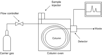
A gas chromatograph relies on a constant flow of carrier gas passing through a 'column', which is in a temperature controlled oven.    You inject the sample gas into the flow at the inlet of the column, and the constituent parts travel through the column at different rates, so the different constituents come out of the column at different times after injection.  See pretty picture from wikipedia article below.

Components of a DIY Chromatograph

Infrastructure

The infrastructure (temperature measurement, temperature control, detector control etc.) can be done using an arduino microcontroller.

Arduino Based Temperature Controller

This was Laura's part of the project - she developed an Arduino programme (sketch) that does the following:
  • Measures the resistance of thermistors (assuming they are wired as a potential divider).
  • Converts the resistance to temperature in degC.
  • Performs 3 term (PID) temperature control by varying an 'analogue' output pin to control the oven temperature (see below for oven details).
  • Outputs relevant data (temperatures etc.) to the controlling computer using the USB serial connection on the arduino.
  • Responds to commands from the USB serial line to change set point, PID gains etc.

User Interface

We had a difficult design choice for user interface - do we write a 'native' user interface on a computer connected to the arduino, or make a web based system?
I decided to go for a web based system, which means that you can use any computer as the user interface, so we need a little web server.   Although some people use Arduino's for this, I thought it would be much easier to use a Raspberry Pi.
We re-cycled the web server code from our Seizure Detector project, which is a simple python web server.
The python programme does the following:
  • Listen for web requests.
  • If no special commands are given, it serves a simple page showing the chromatograph settings and a graph of the temperature history (which will also be the detector output). 
  • The main web page includes javascript code to allow bits of it to be updated without refreshing the whole page every time (the html/javascript code is Laura's).
  • Respond to specific commands (such as change set point) by sending these to the arduino across the serial line.
  • Collect data from the arduino (it sends a set of data every second), and create at time series.
  • Use the time series data to plot a graph of temperature history etc.

The web server code is the python files here: https://github.com/jones139/arduino-projects/tree/master/gc  (execute runServer.py) to start the web server.

The html and javascript based user interface is all here: https://github.com/jones139/arduino-projects/tree/master/gc/www.

The infrastructure part went well - we have a web interface to a three term temperature controller that works fine, and sends data back to the web server, which produces a graph of the temperature history.  You can change set point, controller gains etc over the web interface.

Power Supply and Case

We will need a variety of power supplies (5V for the Raspberry Pi, 12V for heaters, mains for the pump).   I had an old computer case in the Attic, so we used that - it has a power supply that gives 5V, 12V high current, +/-12V and 3.3V, so plenty for what we need.    The case will also house the finished instrument so it will look neater than most of my projects once I put the lid on!
The case for the project!
Case before I removed the old computer boards to make room. - the power supply is at the back.
 The ATX power supply does not start up when the unit is powered on - you needed to press the on button on the case, which energised a line to the power supply via the main computer board.   You can force the power supply to run by shorting a particular pin on the main connector down to ground:


Carrier Gas

To keep things simple I propose to use air as the carrier gas, and use a fish tank air pump to push it through the column.    Because it is a bit noisy, we made the Arduino and web interface allow you to switch it on and off easily.  The pump is mains powered so we used a solid state relay to switch it on and off, and covered the mains connections with plastic to stop us blowing ourselves up with loose wires in the case...
The air pump with sample injector syringe.

Solid state relay mounted in bottom of the case - all the mains connections are covered in clear plastic to avoid them contacting low voltage parts of the equipment.

Oven

For the oven we need an insulated case and some heaters.   For the case we used the old CD drive case from the computer, because it fits in the computer case neatly:

We added some polystyrene insulation to the top to reduce heat loss, and a bit of bubble wrap to the bottom (could not get too much in, or there would be no room in the oven....
The heater element is an aluminium plate cut to the size of the oven with three resistors bolted to it.
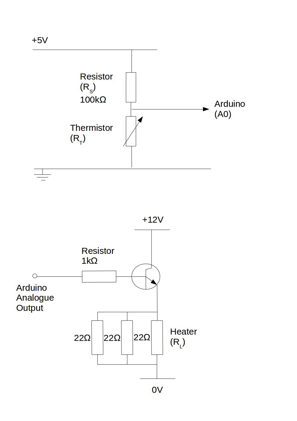
A power transistor is also mounted in the case to switch the current flow to the resistors.  This means that the 12V power supply only has to go to the oven, and we can provide a 5V switching signal from the arduino to control the heater using the transistor:
Heater plate with resistors attached, along with power transistor to control the heater current.   Note that we had to disconnect the transistor heat sink from the plate because grounding it to earth switched on the transistor, so we had an over-heat fault on first commissioning - the arduino tried to switch off the heaters, but they continued at full power - at least we proved that we can get the oven to just over 90degC...
Circuit diagrams for the thermistor measurement and the heater control circuit.

Detector

The detector is my part, and is the bit that is holding up the project at the moment!

First Version - heat loss to environment

My first go was to rely on the gas coming out of the oven being hot, and looking at the amount of cooling of the sample gas compared to pure carrier gas as it passed through some copper tubes:

Unfortunately the gas flow rate is so low that the gas has cooled to ambient temperature before it gets to the detector, so I can't measure anything useful, so need a re-think.

Second version - heated constantan wire

Next, try a hot wire detector - loop of constantan wire used to heat a thermistor using a constant current source - the temperature above ambient should depend on the thermal properties of the gas surrounding it.

Here my lack of practice at electronics design let me down - I made a high current source using a trusty (>30 year old) 741 op-amp and a power transistor.   
Arduino, along with 741 and power transistor current source (the sense resistor is the big grey cylinder above the arduino).  The things in the crocodile clip are the heated and ambient thermistors.

Unfortunately I was using a 100R resistor to sense the current, and my loop of constantan is only about 1R.   This meant that I put a lot more power into the sense resistor than my 'hot' wire - no detectable increase in wire temperature, but smoke and a warming glow from the sense resistor....   Replaced it with the more robust resistor shown in the picture above, which acts as a nice room heater, but no measurable heating of the thermistor.

So, need a higher resistance heater for the thermistor - think I will dismantle a 12V light bulb next....

Summary

Quite an interesting holiday project, but not finished.  
What went well:
  • Working web interface to an arduino temperature controller
  • Working web based data logger.
  • Working oven and switchable pump.
  • Nice case with useful power supply.
  • Laura learned to programme an Arduino, and write javascript web pages

What didn't go well:
  • The detector!
  • I am out of practice at electronics design, and mis-judged heat losses from very very low gas flow rates!